Description
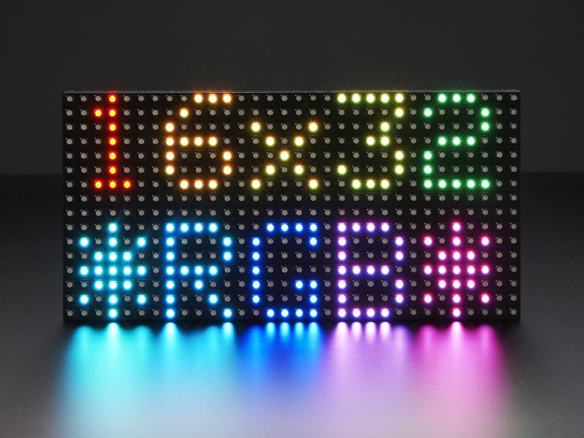
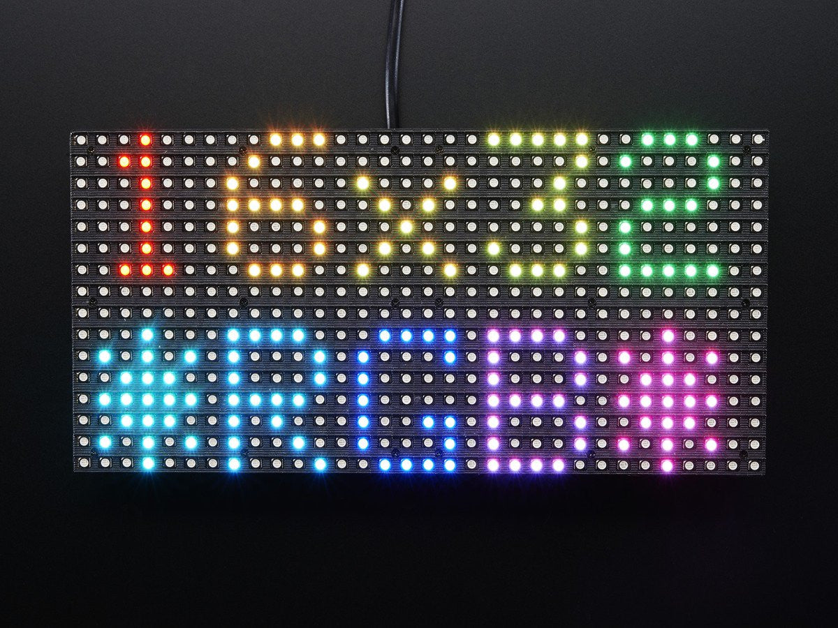
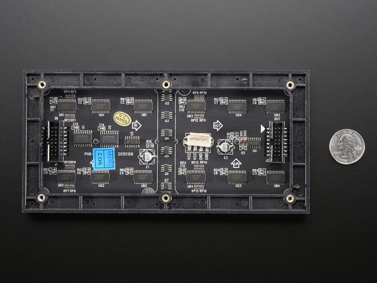
These 16 x 32 RGB LED matrix panels are normally used to make video walls to display animations or short video clips. They have 512 bright RGB LEDs arranged in a 16x32 grid on the front. On the back there is a PCB with two IDC connectors (one input, one output: in theory you can chain these together) and 12 16-bit latches that allow you to drive the display with a 1:8 scan rate. These displays are 'chainable' - connect one output to the next input.
These panels require 12 digital pins (6 bit data, 6 bit control) and a good 5V supply, up to 2A per panel.
Keep in mind that these displays are designed to be driven by FPGAs or other high speed processors: they do not have built in PWM control of any kind. Instead, you're supposed to redraw the screen over and over to 'manually' PWM the whole thing. On a 16 MHz Arduino, we managed to squeeze 12-bit color (4096 colors) with 20% CPU usage but this display would really shine if driven by any FPGA, CPLD, Propeller, XMOS or other high speed multi-core controller. The good news is that the display is pre-white balanced with nice uniformity so if you turn on all the LEDs its not a particularly tinted white.
- 2000 mcd LEDs on 6mm pitch
- 5V regulated power input, 2.5A max (all LEDs on)
- 5V data logic level input
- Dimensions: 192mm x 96mm x 12mm (7.6" x 3.8" x 0.5")
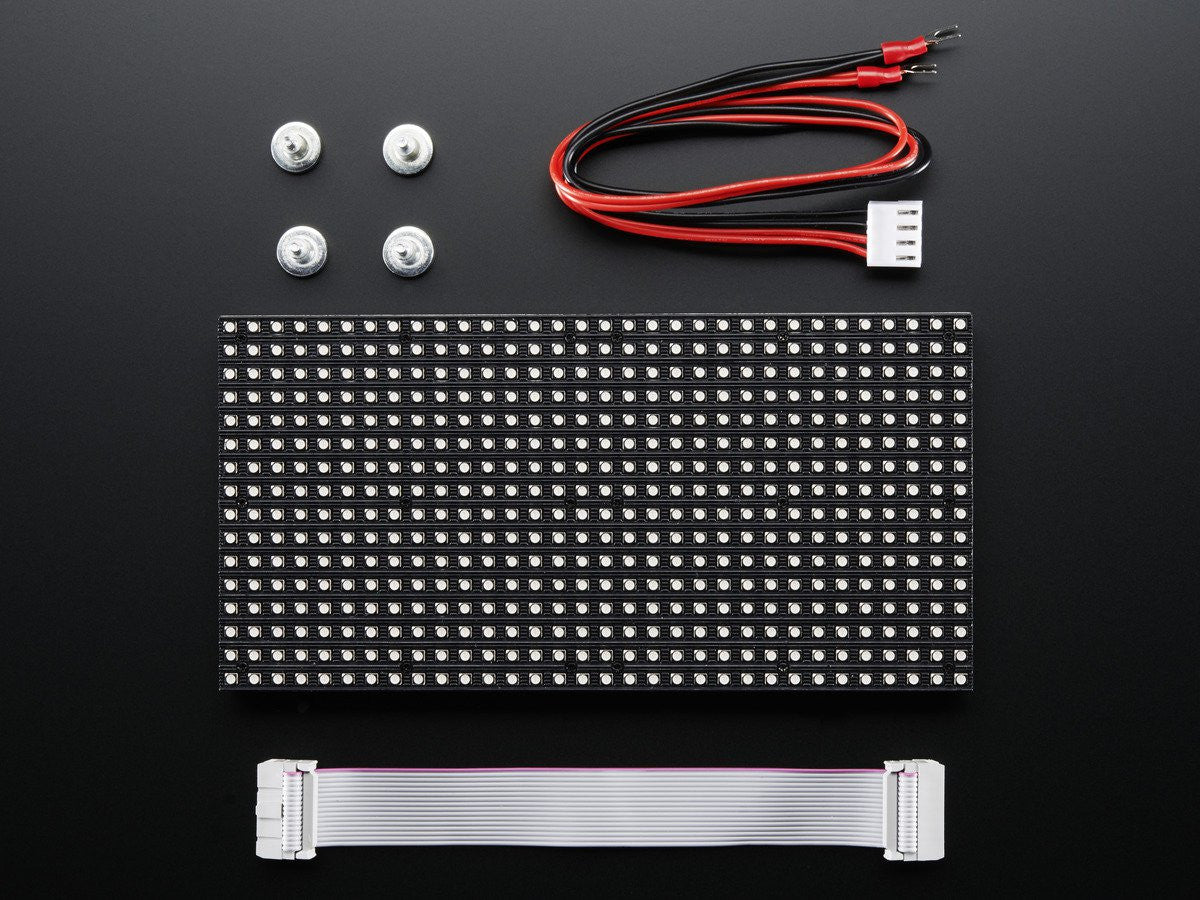
- Panel weight with IDC cable and power cable: 170 g
- 1/8 scan rate
- Indoor display, 150 degree visibility
- Displays are 'chainable' - connect one output to the next input - but our Arduino example code does not support this yet


